Block Diagram In Control System
Block diagrams are a useful and simple method for analyzing a system graphically.
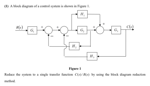
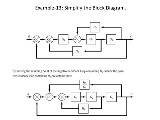
Block diagram in control system. The block diagram representation is a combination of these two methods. However these methods do not work for complicated systems. Block diagram of armature controlled dc motor 67. Each of them has its own transfer function.
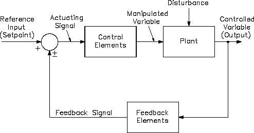
Where transfer function where c s is the output and r s is the input of that particular block. Basic elements of block diagram. Gscsrs where rs laplace transform of the input variable. Step 2 repeat step 1 for remaining inputs.
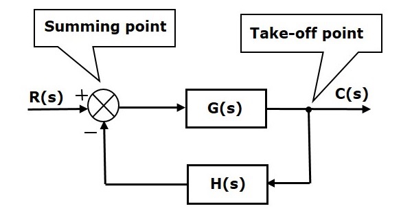
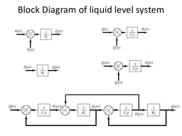
The basic elements of a block diagram are a block the summing point and the take off point. Block diagram of liquid level system 1 1 1 qq dt dh c 1 21 1 r hh q 21 2 2 qq dt dh c 2 2 2 r h q 68. We know that the input output behavior of a linear system is given by its transfer function. Step 1 find the transfer function of block diagram by considering one input at a time and make the remaining inputs as zero.
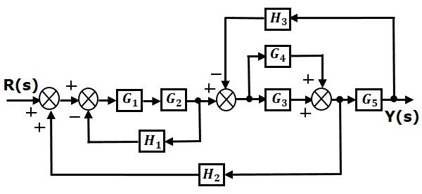
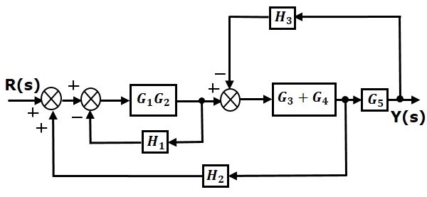
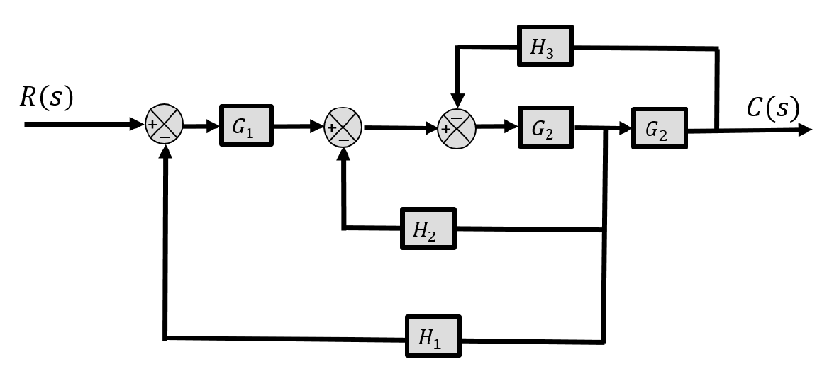
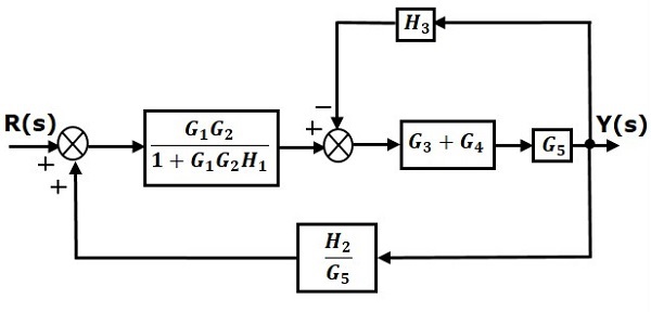
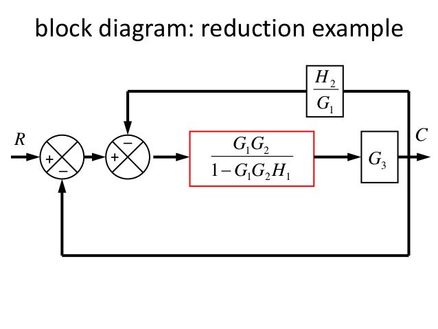
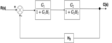
Any system can be described by a set of differential equations or it can be represented by the schematic diagram that contains all the components and their connections. By doing this a set of individual blocks representing the various elements or subsystems is formed and these blocks are interconnected to represent the whole system. It will include block diagram reduction rules some block diagram reduction examples and solutions. There is 1 pending change awaiting review.
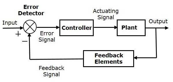
The latest reviewed version was checked on 11 july 2017. Block diagrams of control system. In each block of diagram the output and input are related together by transfer function. A block diagram is high level type of flowchart.
Block diagram for control systems. Block diagram in control systems. Step 3 get the overall transfer function by adding all those transfer functions. A complex control system consists of several blocks.
When designing or analyzing a system often it is useful to model the system graphically. This lecture covers block diagrams used to represent control systems methods of manipulation of block diagrams including an example as well as covering steady state errors and their determination. Block diagram in contol system by using block diagrams when examining larger systems attention can be focused on a smaller number of elements or subsystems whose properties may already be known. These are used to represent the control systems in pictorial form.
