Cooling Valve Wiring Diagram

Cooling Valve Wiring Diagram Wiring Resources

Williamson Relay Wiring Diagram Furnace Thermostat Library I

S Plan Central Heating System Lively Heat Trace Wiring

Ground the control wire of the actuator and the valve should be completely open.
Cooling valve wiring diagram. The o thermostat terminal is for this purpose. Thermostatic wiring principles by bob scaringe phd pe. Diagnose the defective coolant valve n82 n509 or n488 using guided fault finding where stored dtcs are found. So here we show examples of honeywell thermostat wiring diagram 4 wire for these higher wire count t stats.
Auto electric cooling fan wiring part 2 wiring the relays. At no time will the valve port appear to be empty. Replace the defective coolant valve. For people who prefer to see an actual wiring schematic or diagram when wiring up a room thermostat those illustrations are provided here to help understand what wires are being connected and what each wire is doing.
Just an idea on how to wire up electric cooling fans for your vehicle. The following illustrations contain information about engine components filter locations drain points and access locations for instrumentation and engine controls. Using the attached coolant valve installation diagram verify that the coolant valve is properly installed in the heater supply hose with the valve ports in a horizontal position as shown in figure 2 of the installation diagram. Furthermore other manufacturers of heat pumps utilize the reversing valve for cooling.
The electric coolant valve is a directional valve and must be correctly in stalled or it will. Refer back to the diagram often and dont get ahead of yourself. Wiring diagrams you may need to read the following section carefully several times. In either case it is crucial to find the wiring diagram for the unit.
Technical service bulletin. A new system may need as many as ten wires like a two stage heat two stage cooling system heat pump reversing valves fan control etc if the system had two stage heating andor cooling the 2nd stage termainals would be labelled w1 and w2 for heating y1 and y2 for cooling. If possible share the. Finally this is for heat pump thermostats.
These additional terminals are not shown in this diagram. Gm 3 relay lowhigh cooling fan explanationdiagnosis. This wire goes to the outside heat pump condenser for reversing valve control. Plus you had another to feed power to a gas valve or relay to turn the heat on and off.
Here we focus on the 4 wire t stats. By nature of the design of the valve when the coolant valve gate is fully open half of the valve port opening appears to be blocked. But as mentioned todays t stats with their ever growing feature list have more wires to ring out. This article provides room thermostat wiring diagrams for flair honeywell white rodgers and other thermostat brands.

Heat Pump Reversing Valve In 2019 Hvac Maintenance Heat

Taco Zone Valve Wiring Diagram 571 2 Valves
/Page-2459001.png)
Audi Workshop Manuals A6 Quattro Sedan V8 4 2l Art 2000
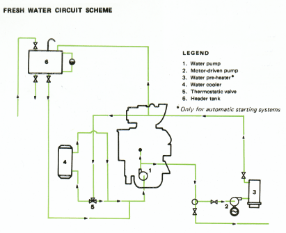
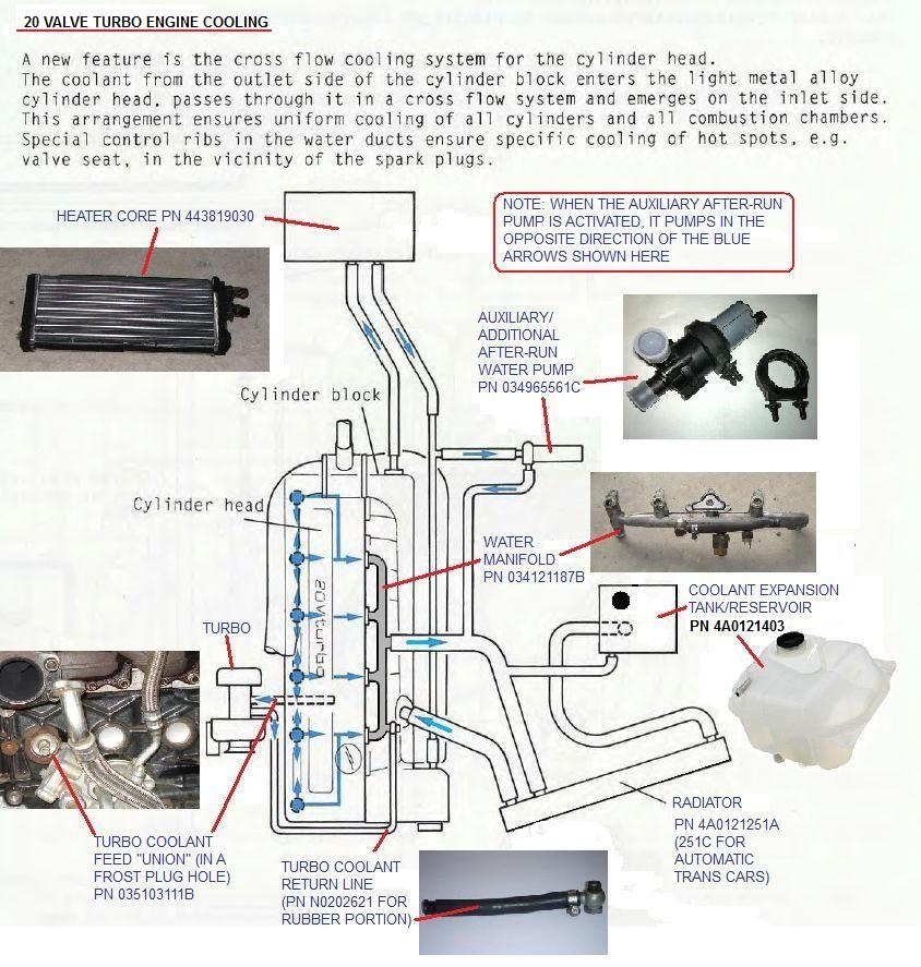
How The Engine Is Cooled

S Plan Central Heating System In 2019 Heating Systems

Uses Of Refrigeration Low Pressure Controls Industrial

Auto Cascade Refrigeration System Hermawan S Blog
/Page-2202002.png)
Audi Workshop Manuals Q7 Quattro V6 3 6l Bhk 2007
Heat Pump New Heat Pump Reversing Valve

Installing Your Ecobee With A Boiler And Ac Dual
C4 Aan Cooling And Heating System With Hyperlinks To More

Ecobee3 Lite Wiring Diagrams Ecobee Support
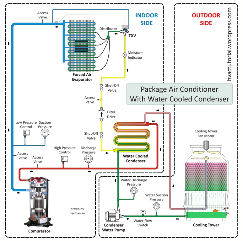
Package Air Conditioning System Hermawan S Blog
Wiring Diagrams Manualzz Com
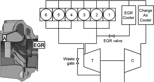
Egr Systems Components

Dometic Single Zone Thermostat Wiring Diagram Free
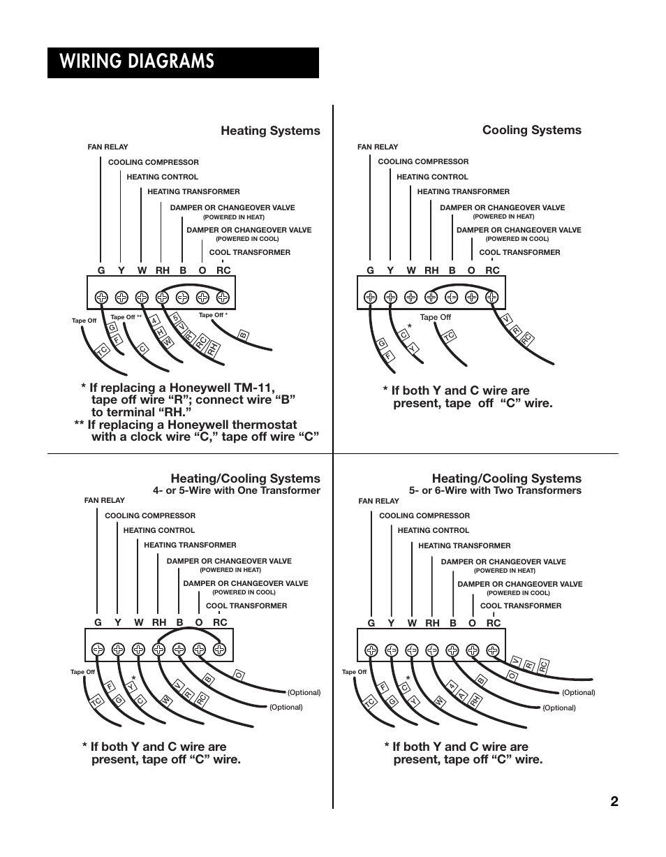
Wiring Diagrams Heating Systems Cooling Systems Lux

2002 Honda Accord Cooling System Wiring Wiring Schematic
