Drum Switch Wiring Diagram
How do i accomplish this.
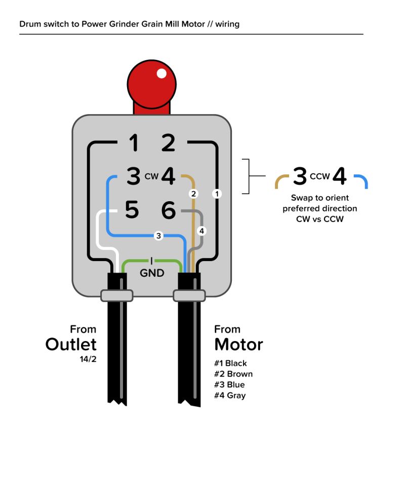
Drum switch wiring diagram. The drum switch look like the old 2x440 at least internal electrically. It is a capacitor start induction run dual voltage motor but with a slight twist. Should be used in conjunction with a motor that has overload protection or where no overload protection is required. Do not over tighten the rubber boot hex nut.
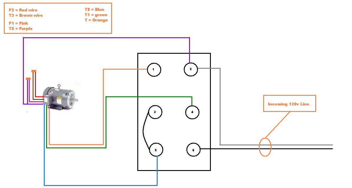
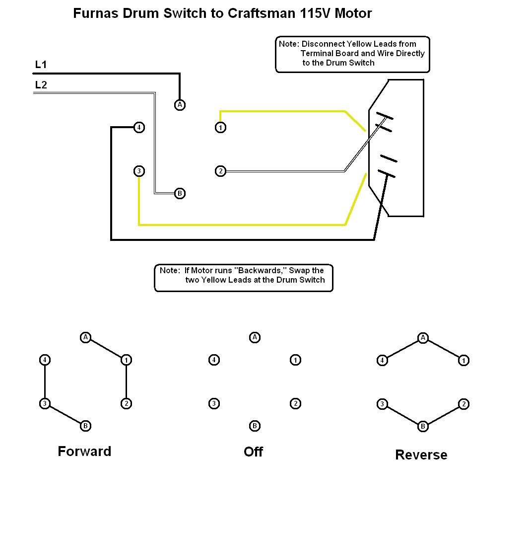
The dayton motor is a little more unusual. It is very similar to this diagram. Electric motor reversing drum switch. It took me waaay too long to figure out how to do this but i reckon itll be worth it.
Align the switch in the front cover and mount the forward stop reverse switch assembly using the rubber boot that is provided. Figure 1 shows a picture of the drum switch and figure 2 shows a diagram of the drum switch contacts. Browse products from schneider electric united states in 2601 reversing drum switches for type a and b reversing drum switches designed for motor rated up to 7 hp. The switch contacts are open and closed manually by moving the drum switch from the off position to the forward or reverse position.
The switch bushing should protrude approximately 015 38mm through the front cover. There are six wires coming from the motor as follows t1 t2 t3 t4 t5 t6t8. For starting ac electric motors forward reverse switch not for instant reverse motors or dc motors metal frame heavy gauge pressed steel grey finish lever plastic or steel made in the usa water tight switch cw0177860s35 ul listed csa certified except rs 1a. How to wire drum switch for reversing single phase 14hp 120v motor.
Dayton drum switches heavy copper drum contacts and metal enclosure with pressed steel case and frame. Remove the jumper assembly that is installed on the. Drum switches and rotary cam switches for starting and reversing of motors. Its not been a huge rush bc the main.


