Franklin Electric Well Pump Control Box Wiring Diagram

Aim Manual Page 54 Single Phase Motors And Controls

Aim Manual Page 54 Single Phase Motors And Controls
How To Wire A Franklin Electric Qd Control Box 1 3 1 Hp

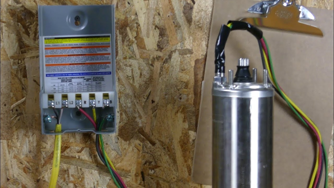
This video shows wiring a franklin submersible pump control box.
Franklin electric well pump control box wiring diagram. Control box wiring diagrams continued cookies. The diagrams for both the two and three wire pumps can be downloaded using adobe. In this video chris shows you how to wire the franklin electric qd control box. And directly from franklin electric.
Call franklin toll free 800 348 2420 for information. Franklin electric control box wiring diagram. 3 wire well pump wiring diagram sample. Key dealer program learn more.
And directly from franklin electric. Warning serious or fatal electrical shock may result from failure to connect the motor control enclosures metal plumbing and all other metal near the motor or cable to the power supply ground terminal using wire no smaller than motor cable wires. Franklin electric aim. All 3 wire submersible pumps from 13 up to 1 hp utilize a qd control box to start the pump.
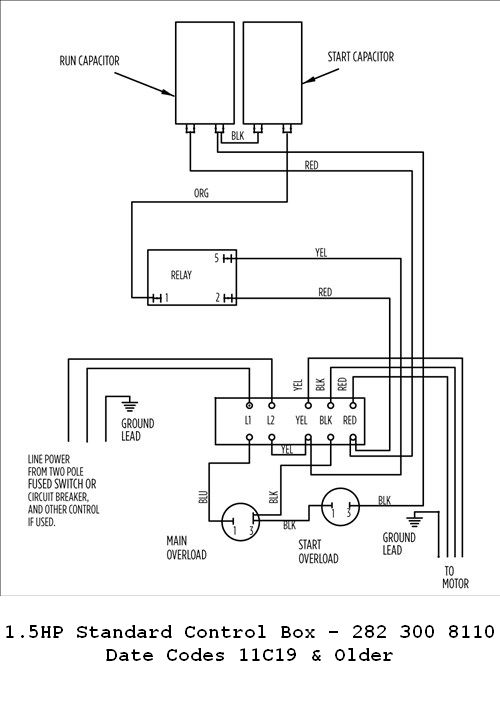
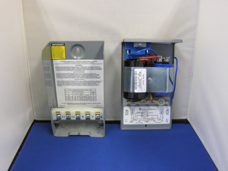
Franklin electric submersible control boxes are designed and optimized specifically for franklin three wire single phase motors rated 13 to 15 hp. Single phase submersible pump control box wiring diagram 3 wire submersible pump wiring diagram in submersible pump control box we use a capacitor a resit able thermal overload and dpst switch double pole single throw. Here is the complete guide step by step. Franklin electric control box wiring diagram.
To replace the two wire pump. Our website uses cookies for analytics and to enable dynamic contentlearn more. The green ground wire should also be terminated to the box and a ground coming from the panel. Submersible pump control box wiring diagram image.
Pump selection find the right pump for you. Franklin electric control box description franklin electric submersible control boxes are designed and optimized specifically for franklin three wire single phase motors rated 13 to 15 hp. Call 1300 franklin for information. Heavy duty box type terminals accept up to awg 2 wire.
Wiring diagram franklin electric control box refrence wiring diagram. The wiring connection of submersible pump control box is very simple. Warning serious or fatal electrical shock may result from failure to connect the motor control enclosures metal plumbing and all other metal near the motor or cable to the power supply ground terminal using wire no smaller than motor cable wires.

Aim Manual Page 54 Single Phase Motors And Controls

Aim Manual Page 54 Single Phase Motors And Controls
1 1 2 Or 1hp 230v Standard Control Box W Overload

Submersible Pump Control Box Wiring Diagram For 3 Wire

Troubleshooting Residential Submersible Pump Systems

Wire Diagram For A Franklin Electric Submergible Pump Fixya

Wiring Diagram For 220 Volt Submersible Pump Submersible

3 Wire Vs 4 Wire Submersible Pump Doityourself Com
1hp 230v Crc Control Box

Franklin Electric 2823008110 1 5 Hp Standard Control Box 230 Volt

Franklin Electric Control Box Anansistudios Co

Franklin Electric 2822029330 10 Hp Deluxe Control Box 230 Volt

2014 08 21 Well Pump Control Box

Wiring Diagram For 220 Volt Submersible Pump Wiring

Franklin Electric Well Pump Wiring Diagram Series Curve

Red Lion Rlcb10 230 1 Hp 230 Volt Vmc Well Pump Control Box

2 Wire Vs 3 Wire Well Pump Motors
Franklin Qd Control Box 1 Hp 230 Volts 1 Phase 2801084915
