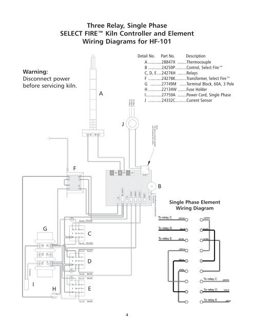
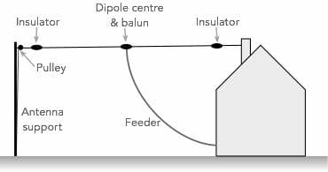
Hf Wiring Diagram
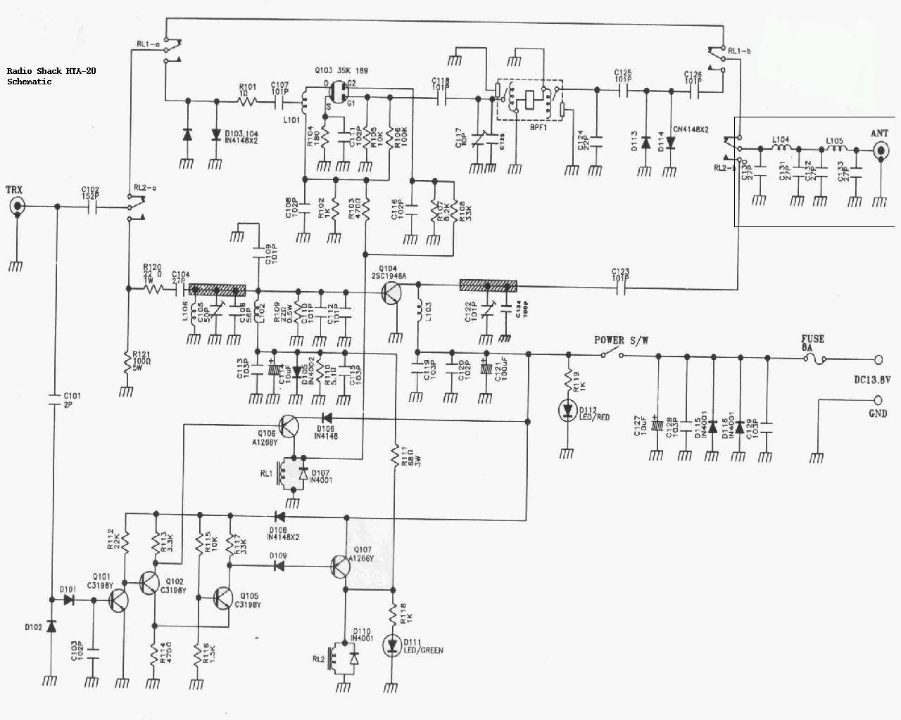
The fiat lancia delta hf speedometer drive motor is of the synchronous direct current type and is controlled by an electronic control unit located in the instrument panel based on the frequency of the signals emitted by the impulse.
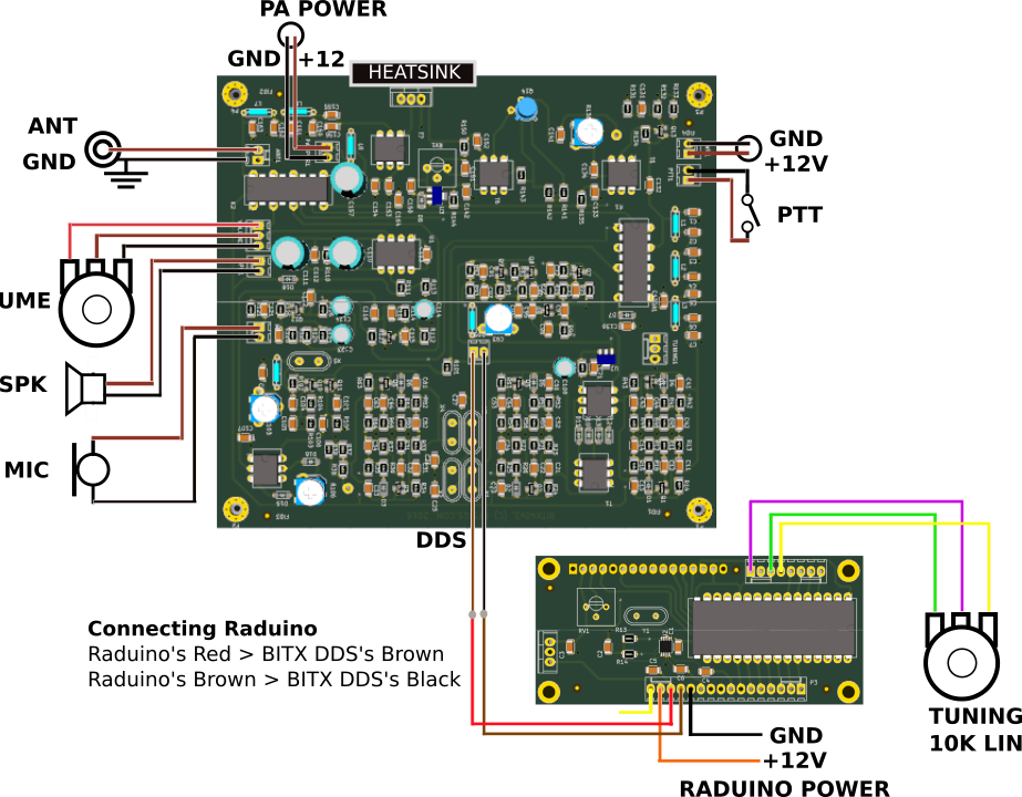
Hf wiring diagram. The brown wire should go to 12v line from the power supply and the black wire should go to ground line of the power supply. Solder the digital connectors blue wire to the tip tab of the cw key socket. Di 8x24vdc hf 6es7131 6bf00 0ca0 manual 122017 a5e03576305 ae preface documentation guide 1 product overview 2 wiring 3. The green wire from the digital connector carries 5v.
The cw key needs a pull up resistor of 47 k from 5 volts to the key sockets tip. Posted by circuit diagram in automotive wiring. The supplied dc socket can be hooked to the dc power lines. Digital input module di 8x24vdc hf 6es71316bf00 0ca0.
Properties wiring diagrams characteristics and technical specifications. The setting of this control will vary depending on how far away. Fiat lancia delta hf electronic speedometer wiring diagram. The blue wire of the digital connector is the keyer line a6 of raduino.
Astatic communication microphones wiring diagrams and more. This control should be adjusted so that the level indicated on the vu meter does not exceed 3 on voice peaks. Use a two wire connector as shown in the diagrams upper right side to supply 12v power to the board.
