Hydraulic Elevator Schematic Control Diagram

How to use in this video lift power and control wiring this video.
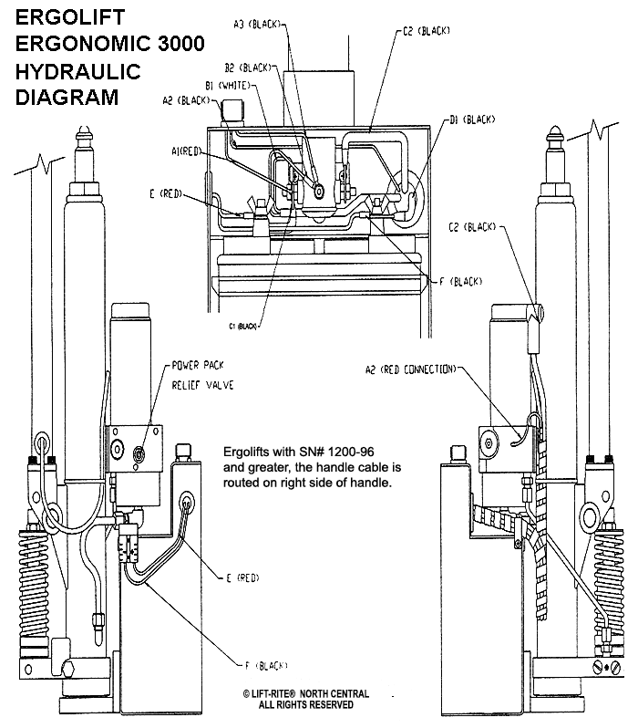
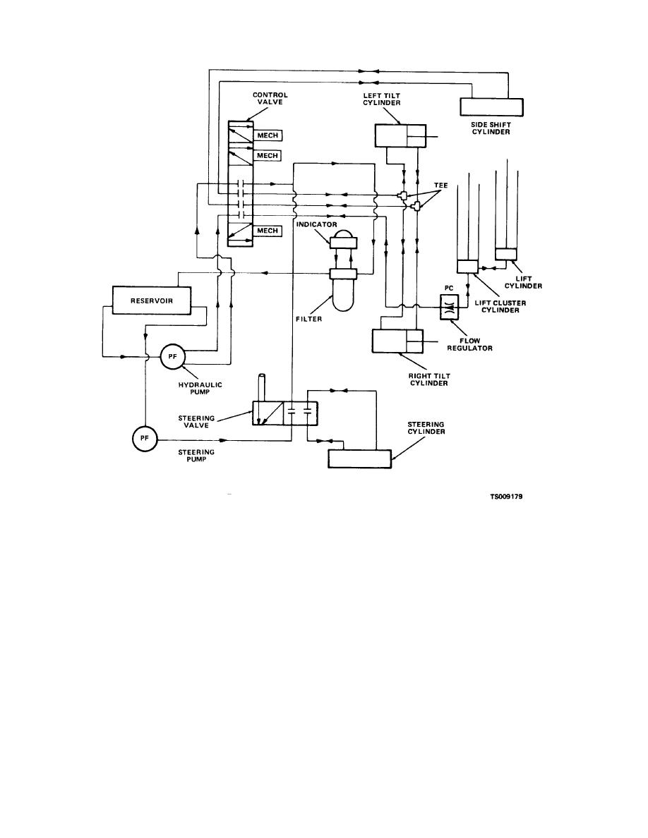
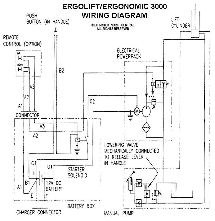
Hydraulic elevator schematic control diagram. This video shows a relay logic elevator circuit diagram and how relays work in slow motion. Reading and interpreting hydraulic schematic symbols page 11 sullivan pressure control symbols hydraulic pressure is controlled through the use of valves valves that open and close at different times to allow fluid to be bypassed from points of high pressure to points of low pressure. Elevator control switch industry application ia00801001e april 2007. For mid and high rise buildings traction or cable driven type of elevators are perfectly suitable compared with the electromechanical relays based elevators and hydraulic elevators.
Reviewing the circuit diagram and relating the trouble symptoms. The primary difference is that a hydraulic elevator uses a hydraulic piston to raise and lower the elevator car while a traction elevator uses a geared or gearless hoist machine along with a counterweight to control the travel of the car. There are two major elevator designs in common use today. Elevator anatomy schematic of traction hydraulic elevator systems.
They are used for low rise applications of 2 8 stories and travel at a maximum speed of 200 feet per minute. For computer laptop. Hydraulic elevators and roped elevators. Hydraulic training associates provides more then just training we can re draw your schematics and supply them to you animated and in an mp4.
The elevator works by a three phase power circuit which supplies the motor and a low voltage control. Elevator controller wiring diagram thanks for visiting our site this is images about elevator controller wiring diagram posted by ella brouillard in elevator category on oct 08 2019. Hydraulic elevator systems lift a car using a hydraulic ram a fluid driven piston mounted inside a cylinderyou can see how this system works in the diagram below. Hydraulic elevators are supported by a piston at the bottom of the elevator that pushes the elevator up.
Proper schematic design building a schematic is. Shunt trip device wiring diagram shunt trip device from feeder l1 l2 l3 battery lowering device. The machine room for hydraulic elevators is located at the lowest level adjacent to the elevator shaft.


