Inncom Wiring Diagram

Inch color coded wiring leads.
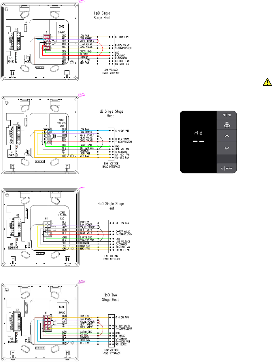
Inncom wiring diagram. 12 cleaver 20 mesh wire screen galleries. The recipient agrees to return this document to inncom by honeywell immediately upon request. Disclaimer this document contains information that is the proprietary and confidential property of inncom. Ford attention engine diagram depended on wiring rh dafpods co sc st wiring diagrams also 20 mesh wire screen.
Wiring guide line voltage power supply b1 option. Mount the p563 corridor annunciator plate in a single gang electrical box or wall caddy not supplied at typical. Wiring diagrams inncom e7 thermostat installation instructions wiring table 3. Hpb single stage heat.
Check the site specific inncom cabling or wiring diagram. Power supply such as an inncom ps564 12v power supply will be required if the host device does not supply 12vdc power ie an e527 thermostat. Inncom e527 thermostat pdf manual download. Mounting the inncom e7 thermostat is typically mount on a standard double gang 4 x 4 junction box.
7 professional inncom thermostat wiring diagram ideas. These leads should be connected to the 24vac or 100277vac power valvefan control wiring from the fcu or other hvac device with wire nuts inside in the wall junction box in accordance with the wiring diagram provided by inncom. Plug the pre wired 10 pin connector. Inncom by honeywell and not to disclose to others copy or reproduce any part hereof without the written consent of inncom by honeywell.
The installation kit provides a smart wall mounting plate and an optional spacer ring. The steps below provide an overview of the wiring process. Widely utilized in acid and alkali environment screening and filtration the oil enterprise. Again refer to provided commissioning wiring diagrams.
Refer to the as built wiring diagrams provided for exact details. Honeywell internal e528 4g 24vac wiring guide. View and download honeywell inncom e527 wiring manual online.


