Radio Diagram Circuit

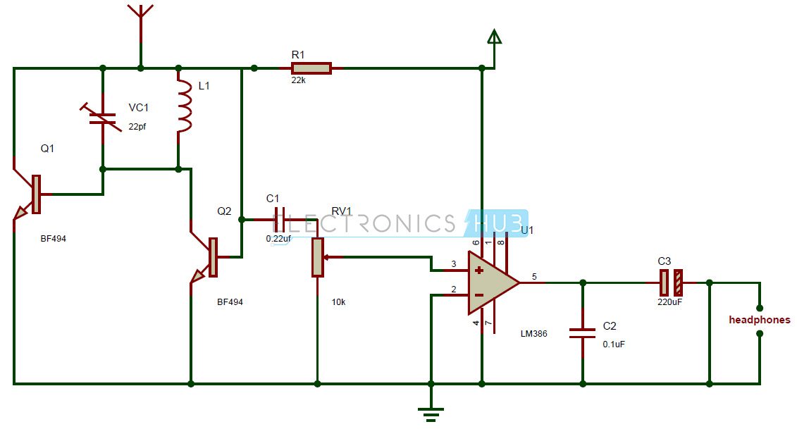
Small Fm Radio Circuit
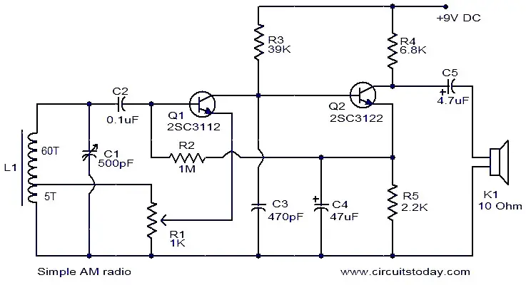
Simple Am Radio Electronic Circuits And Diagrams
Fm Radio Circuit Tiny Single Chip Fm Radio

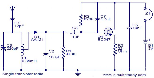
The main principle of this circuit is to tune the circuit to the nearest frequency using the tank circuit.
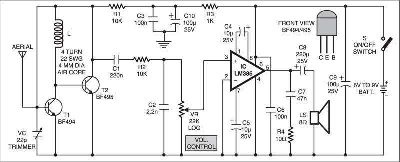
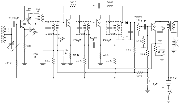
Radio diagram circuit. The signal is then filtered by c3 so that only the audio signal will be amplified by t2. Data to be transmitted is frequency modulated at the transmission and is demodulated at the receiver side. The circuit use a compact three transistor regenerative receiver with fixed feedback. Variety of kenwood radio wiring diagram.
The amplified signal is then delivered to a high impedance earphone. Fm radio circuit principle. 20000 dial stringing diagrams all truely free with no login required. An antenna ground system tank circuit peak detector and headphones are the the main components of a crystal radio.
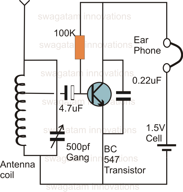
A wiring diagram is a streamlined conventional photographic depiction of an electric circuit. The circuit is designed around the ic zn414z which is a ten transistor tuned radio frequency receiver the ic has only three leads and is available in the to92 package. Simple fm radio circuit using a single transistor last updated on october 6 2019 by swagatam 158 comments when it comes to making an fm receiver its always thought to be a complex design however the one transistor simple fm receiver circuit explained here simply shows that it isnt the case after all. All necessary circuits required for an am receiver rf amplifier detector and agc are incorporated inside the icin the circuit given below capacitor c1 and resistor r1 forms.
Remote controlled home appliances. Home appliances lamp fan radio etc to make the appliance turn. Beitmans includes free schematic diagrams for tube radios tube phonographs vintage transistor radios vintage transistor phonographs. Here is the circuit diagram of remote operated home appliances or.
It is similar in principle to the zn414 radio ic which is now replaced by the mk484. Transistor radio circuit schematic. The combination of c1 and l1 comprise a resonant circuit refered to as a tank circuit. All general purpose transistors should work in this circuit you can use bc549 transistors for this circuit.
The coil is 65 turns am antenna wire around a 10 cm long x 10 mm diameter ferrite rod. Full set of tube base diagram tube manuals from 1920 to 1975 full set of addison radio schematic diagram tuning manuals. It shows the elements of the circuit as streamlined shapes as well as the power and signal connections between the devices. Connect this circuit to any of your.
The demodulated signal comes out from the collector of t1. The circuit can be activated from up to 10 meters. This is the circuit diagram of mini am radio receiver. Radio is the reception of electromagnetic wave through air.
The antenna absorbs transimtted radio signals b which flow to ground via the other components. A good design will usually have low impedance taps on the inductor for connections to the antenna and diode as shown in the schematic. See figure above a.

Three Transistor Radio Circuit Diagram

Two Transistor Am Radio Receiver Circuit

Three Transistor Radio Circuit Diagram

Simple Fm Radio Circuit With Speaker In 2019 Electronic

How To Make Fm Radio Circuit Electronics Projects Hub
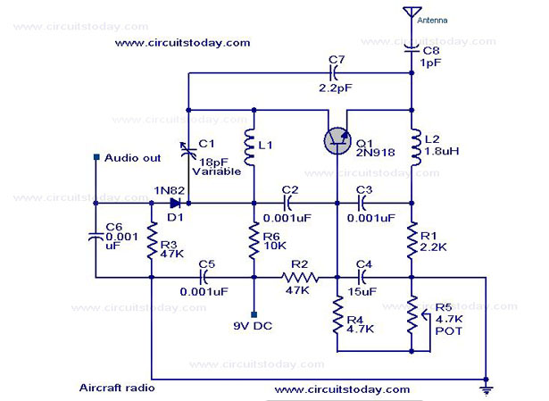
Simple Aircraft Radio Circuit Circuit Diagram Working

The Circuit Of A Simple Radio Receiver 9 Download
Fm Receiver Electronics Circuit With Full Explanation
Single Transistor Radio Electronic Circuits And Diagrams

Three Transistor Radio Circuit Diagram
Radio Circuits Practical Analog Semiconductor Circuits
One Transistor Radio Circuit Diagram

Two Transistor Am Radio Receiver Circuit Schematic In 2019

Schematic Diagram Of Fm Radio Wiring Diagrams

Fm Radio Receiver Circuit
Simple Radio Diagram Wiring Diagrams

Pc Fm Radio Circuit

Radio Circuit Diagram Wiring Diagram Schematics
