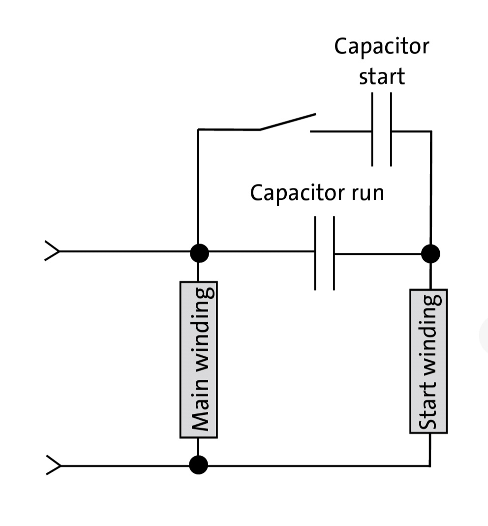
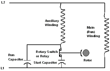
Wiring Diagram For Capacitor Start Capacitor Run Motor

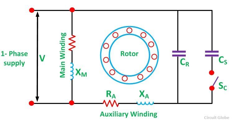
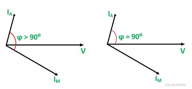
Figa shows the phasor diagram when at the starting both the capacitor are in the circuit.
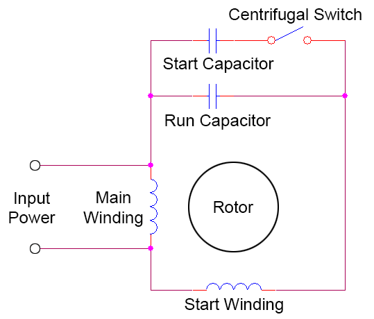
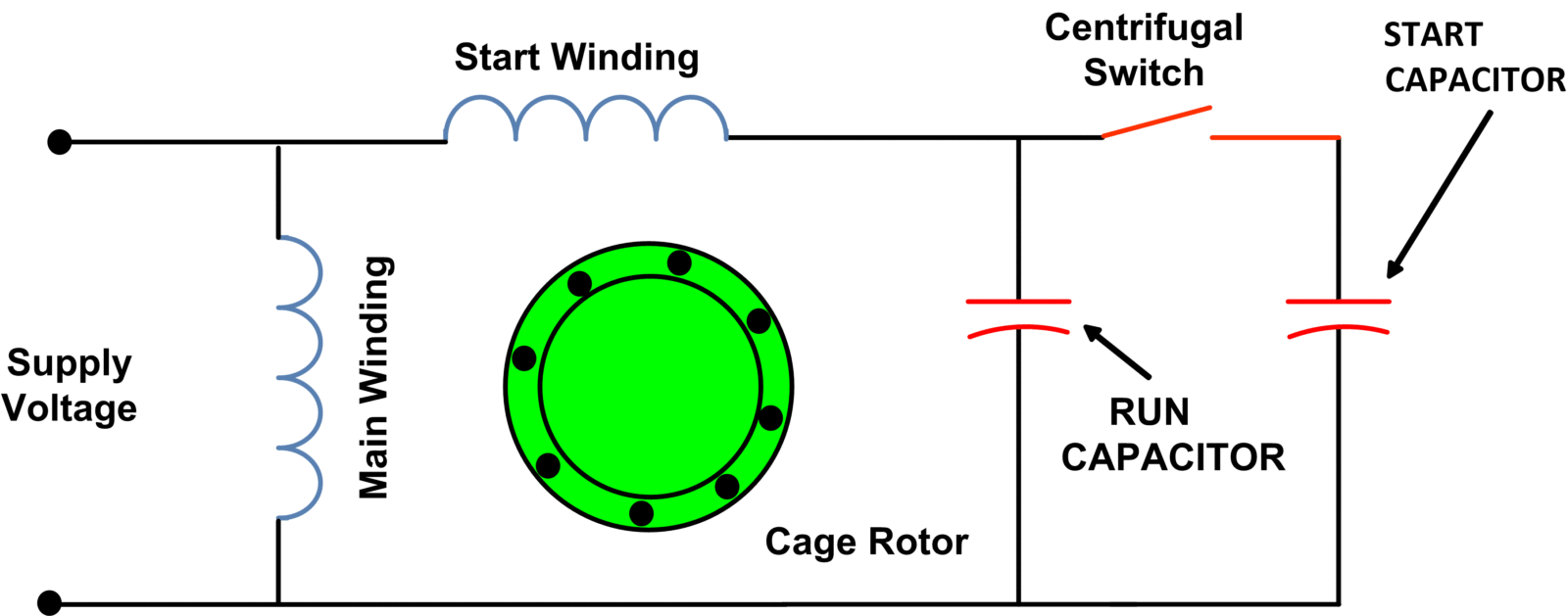
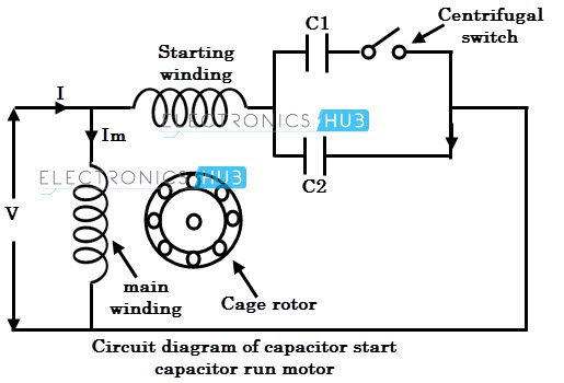
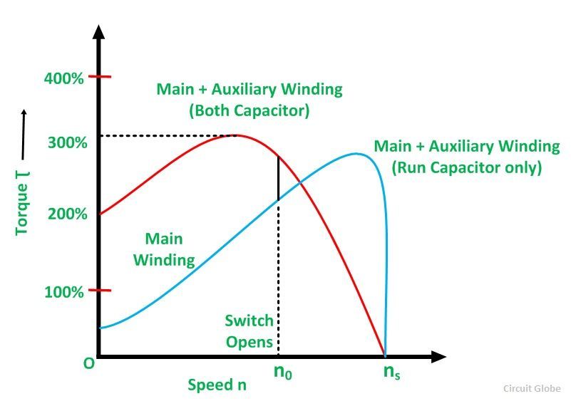
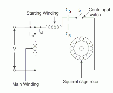
Wiring diagram for capacitor start capacitor run motor. Start capacitor run capacitor or permanent capacitor. Also read about the speed torque characteristics of these motors along with its different types. The figure below shows the phasor diagram of the capacitor start capacitor run motor. Click here to view a capacitor start motor circuit diagram for starting a single phase motor.
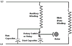
Push the wire terminal on the start capacitors second wire onto the run capacitors common terminal often labeled c com the wire connected to the motors run terminal marked as r on the motors wiring chart and the wire going to the hot terminal on the load side of the contactor also connects to this run capacitor terminal. Wondering how a capacitor can be used to start a single phase motor. Each component should be placed and connected with other parts in particular manner. Why we applied a capacitor for single phase induction motorthe reason is to improve performance of motor by generate the rotating fielddesign for this motor have a two 2 stator windingand one of it is the auxiliary and is connected by a suitable.
Learn how a capacitor start induction run motor is capable of producing twice as much torque of a split phase motor. The run capacitor is long time rated and is made of oil filled paper. How to wire single phase motor with capacitor. The capacitor c r is connected permanently in the circuit and thus it is known as run capacitor.
If not the structure will not work as it should be. You will find out how to identify to main and auxilliary winding and change motor rotation. However some people still struggle with the wiring part of the motor to the capacitor.
