York Ga Valve Wiring Diagram

York Gas Valve Wiring Diagram Wiring Diagram
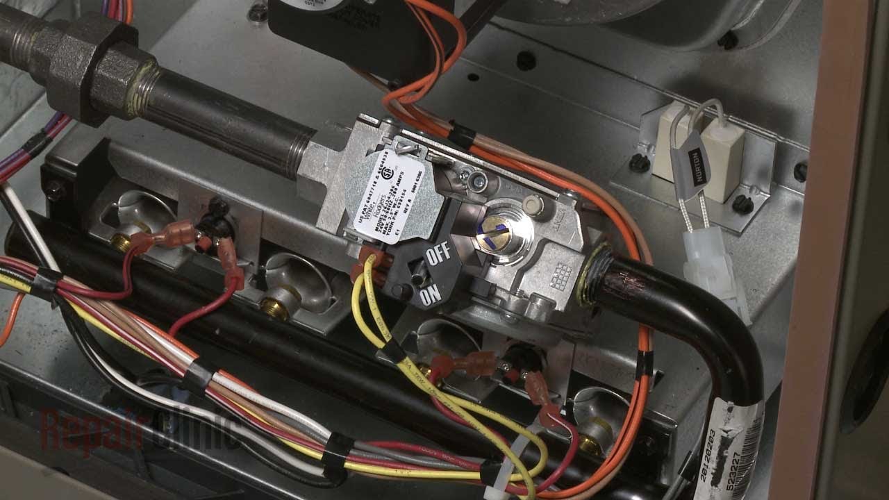
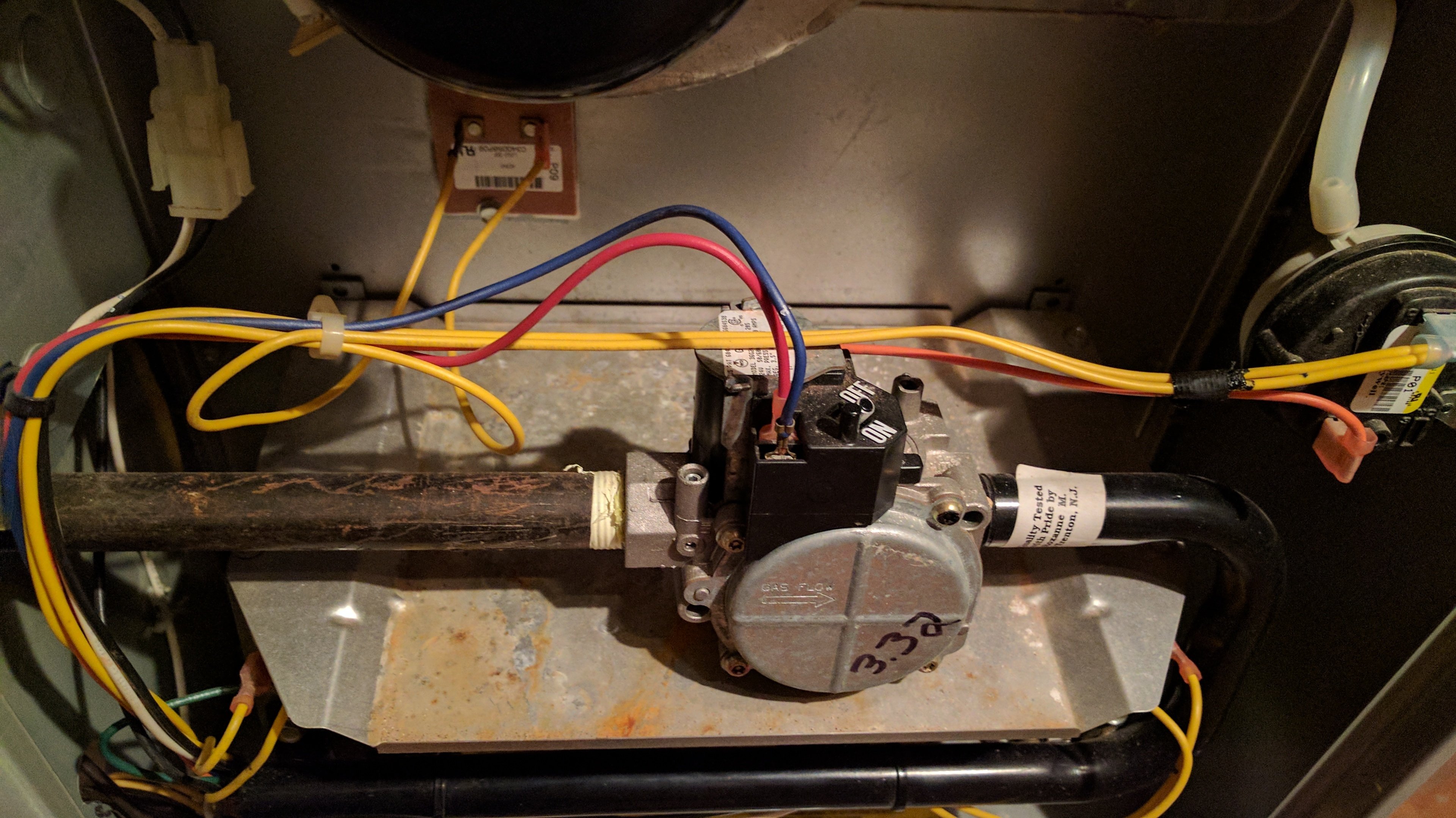
York Furnace Gas Valve Assembly Replacement S1 32544123000

York Diamond 80 Manual Reset

This material is for professional use only and is intended to be used only as reference material by licensed contractors when installing or servicing reznor equipment.
York ga valve wiring diagram. Gas pressure may be measured by connecting the regulator pressure switch adjustment u tube manometer to the gas valve with a piece of tubing. 1183746 uim b 0215 main burner operation flame present with gas off the control board keeps the main gas valve and induced draft motor if flame is sensed for longer than 40 seconds during a period when the energized while continuously monitoring the call for heat pressure gas valve should be closed. View and download york tp9c series installation manual online. Variety of white rodgers gas valve wiring diagram.
Modulating ecm residential gas furnaces. It shows the elements of the circuit as simplified shapes and the power and signal links in between the tools. This video is part of the heating and cooling series of training videos made to accompany my websites. By andy johnson december 8 2015.
The gas valve body is a very thin casting that cannot take any use the wiring diagram below to c onnect the furnace control communi wiring diagrams index legend unit type voltage 1 ph 60 hz figure no. York pcg4 series installation manual. Typical wiring diagram manual indoor gas fired unit heaters and duct furnaces standard natural vent or power vented. This tip is about the basic terminal designations on typical 24v gas valve.
Jesse grandbois is one of the techs who reads the tech tips and he wrote a few tips that he wanted to share on some gas furnace control basics. 18 m of the furnace. Nortek global hvacreznor does not endorse any field changes to factory wiring schemes. This one covers how the gas valve on the millivolt system is wired.
Follow the appropriate section in the instructions below. Each unit heater duct furnace. Gas furnace wiring diagram york. Wiring diagram wiring.
Have you ever noticed the th tr terminal on a. Furnace should be located as close to the gas valve and controls as possible. A wiring diagram is a streamlined conventional pictorial depiction of an electrical circuit.
Unique Mid Position Valve Wiring Diagram Racemaster

Gas Valve York Furnace Gas Valve Problems

Gas Heating Gas Valve Or Circuit Board Heating Help

York Wiring Schematics Wiring Schematic Diagram

Troubleshooting Heating Older Sunline Units York Central

York Gas Furnace Wiring Diagram Wiring Diagram

How To Install Wire The Fan Limit Controls On Furnaces

Troubleshooting Heating Older Sunline Units York Central
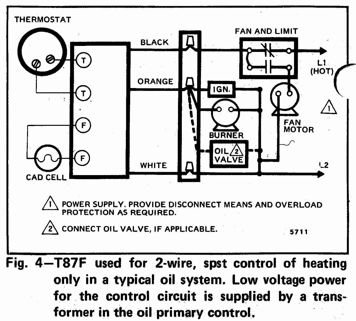
Room Thermostat Wiring Diagrams For Hvac Systems

Furnace Gas Valve Wiring Diagram Wiring Schematic Diagram
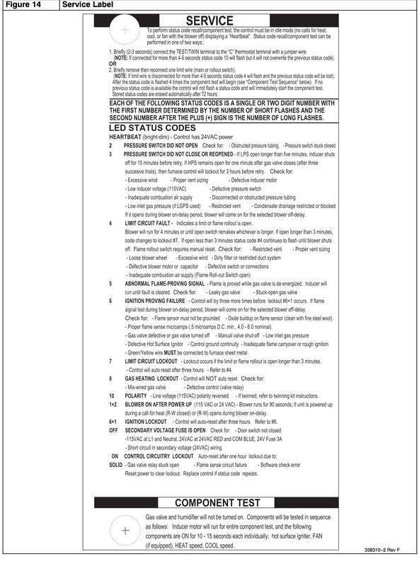
Gas Furnace Fault Or Error Codes For Common Furnaces Gray

York Diamond 80 Furnace Installation Manual

Looking For York Model P1cxd12n06401 Furnace Repair

Gas Valve Failure Heating And Air Omaha Accurate Heating
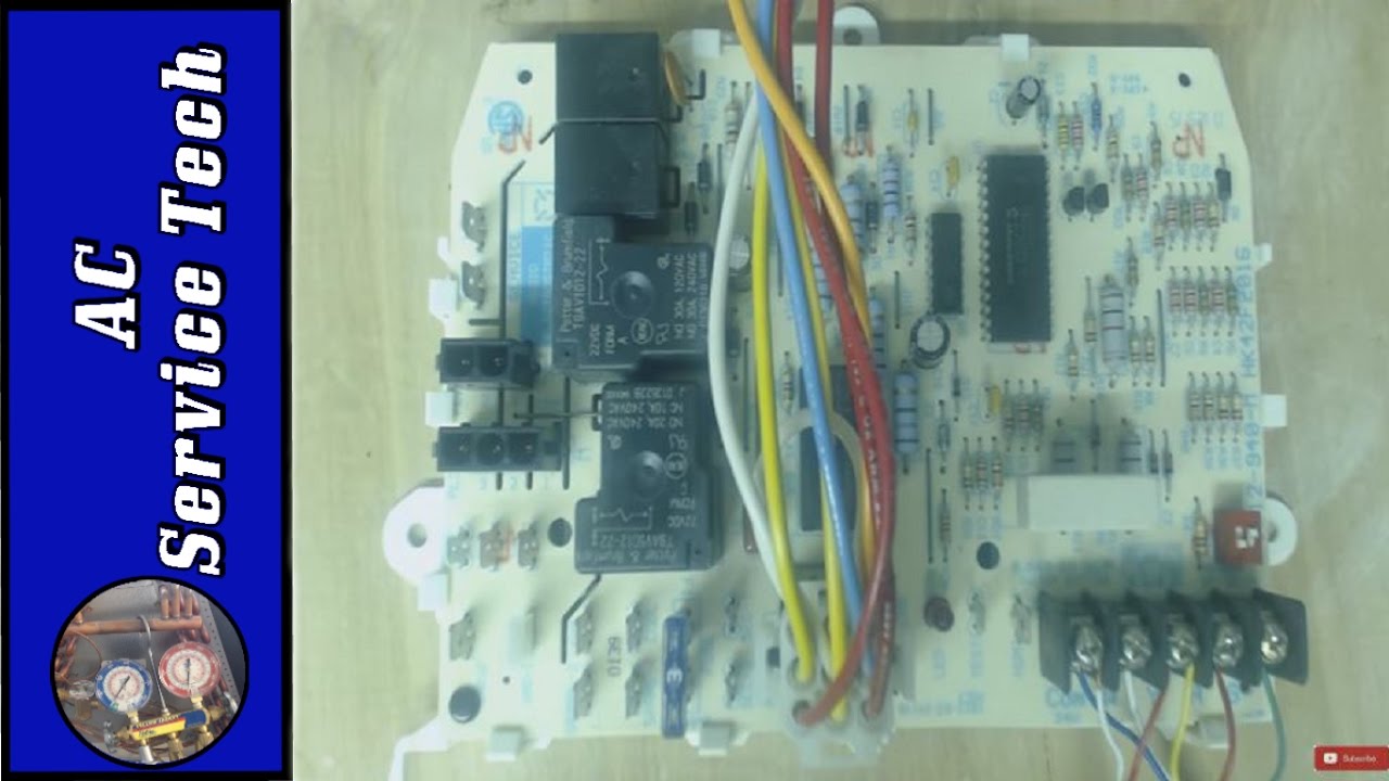
Troubleshooting The Furnace Control Board Ifc To Test If Its Bad For Heat And Ac Diagnosis

Unique Mid Position Valve Wiring Diagram Racemaster

Th Tr And Th Tr Gas Valve Terminals Hvac School
Gas Heating Gas Valve Or Circuit Board Heating Help
