4 Way Switch Wiring Diagram Power At Switch

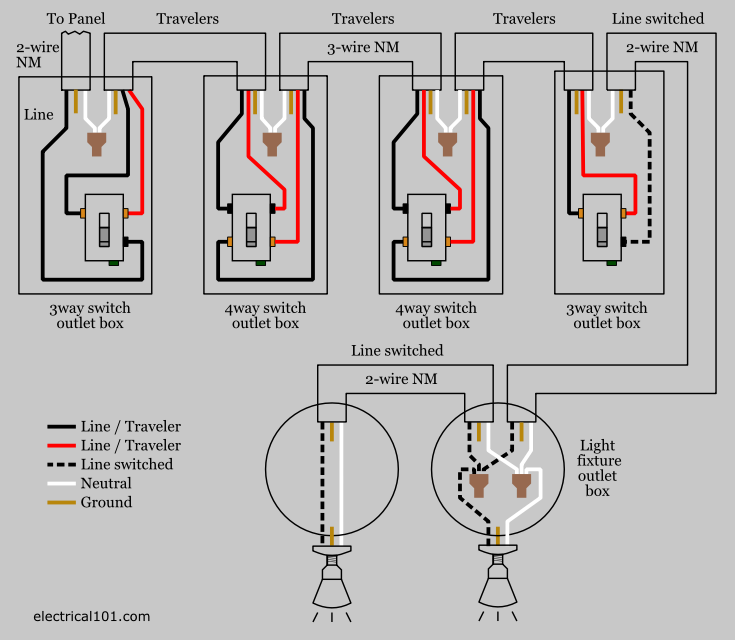
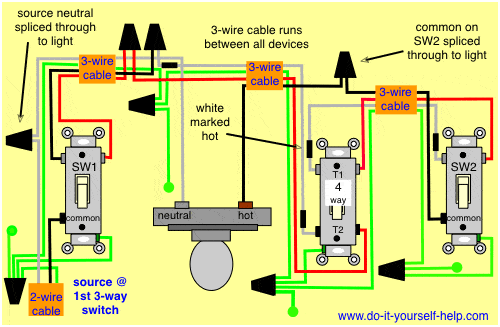
In this circuit the power comes in through the first switch.
4 way switch wiring diagram power at switch. I have a few of the most common ways in wiring a 4 way switch to help you with your basic home wiring projects. The 4 way is used when you want to control the light or lights from two or more locations. Unfortunately not all 3 way switches are wired the conventional way. A 4 way switch wiring diagram is the clearest and easiest way to wire that pesky 4 way switch.
Click here to access note. The white wire of the cable going to the switch is attached to the black line in the fixture box using a wirenut. To view it at full size click on the diagram. Wiring a 4 way switch with light at.
For circuits that control lights from two locations only check the wiring diagrams at this link. This diagram is a thumbnail. Basic 3 way switch diagram plans instructions how to wire a 3 way switch step 1. More about wiring a 4way switch.
Turn the power off at your breaker box. The first step in any electrical project is to make sure there is no power going to the circuit you plan to be working on. See alternate 3 way switch wiring configuration for another way 3 way switches may be wired. First of all we need to go over a little basic terminology on switches.
Check here for 4 way switch troubleshooting and help with 3 ways switches here. 4 way switch wiring diagram with the power feed through a switch. The diagrams below show the conventional wiring for 3 way switches in a 4 way configuration. Included are a 4 way dimmer switch diagram and an arrangement that can be used to control room lights from four different locations.
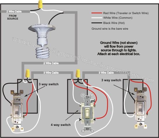
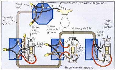
If you have any problems with these switches it may be best to call an electrician. For complete instructions on wiring a basic 4 way switch see our wiring a 4 way switch article. This 4 way switch diagram 2 shows the power source starting at the fixture. The white wire becomes the energized switch leg as indicated by using black or red electrical tape.
The hot is connected to the common on the switch and the neutral is spliced to all the switch boxes through the neutral terminal of the light.


