Camper Plug Wiring Diagram

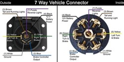
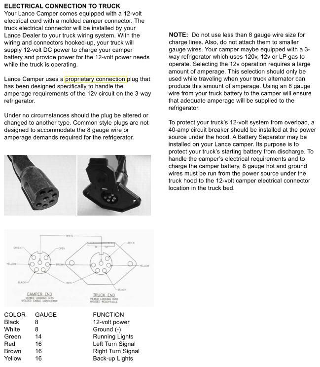
Below is the generic schematic of how the wiring goes.
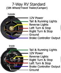
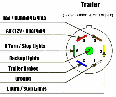
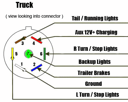
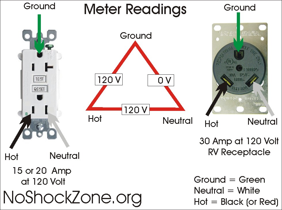
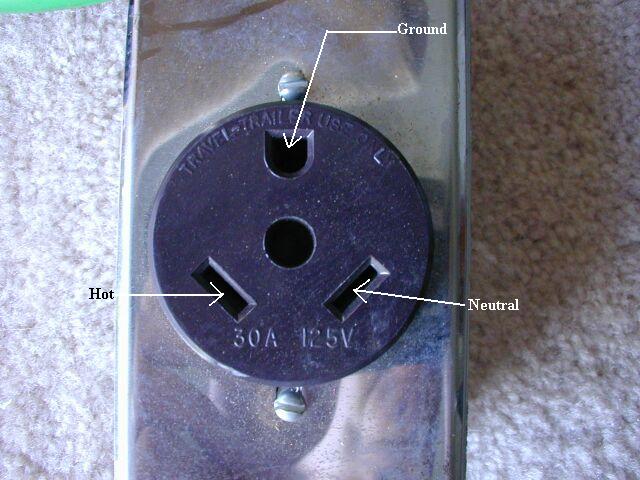
Camper plug wiring diagram. 7 way plug wiring diagram standard wiring post purpose wire color tm park light green battery feed black rt right turnbrake light brown lt left turnbrake light red s trailer electric brakes blue gd ground white a accessory yellow this is the most common standard wiring scheme for rv plugs and the one used by major auto manufacturers today. Wiring a 30 amp rv plug to a preexisting umbilical from the rv is a simple matter and can be accomplished with normal household electrical tools. A wiring diagram is a streamlined conventional photographic depiction of an electrical circuit. This universal wiring kit lets you install an electric brake controller sold separately in your vehicle and a 7 way connector for your trailer lights at the same timeplugs into the existing 4 way drive a crew cab extended cab with long bed cargo van or extended length suv extra wire etbcxw sold separately will make installation much easier.
Above we have describes the main types of trailer wiring diagrams. Use the 7 pin connector anyway see below and just leave out the last 2 wires. Each tail lamp assembly at the back of the trailer also must be grounded. Need to know which color wire go to which post.
The 30 amp rv plug is colloquially known as an rv 30. When wiring a trailer connector it is best to wire by function as wire colors can vary. Stop into our harrisburg pa dealership today or call to learn more. 4 5 way flat connector wiring diagrams.
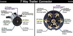
7 way rv trailer connector wiring diagram. The trailer wiring diagrams listed below should help identify any wiring issues you may have with your trailer. 4 pin trailer wiring diagram. 4 way and 5 way flat connectors use color coded wires and are available in a variety of lengths.
It reveals the elements of the circuit as simplified forms and also the power as well as signal links between the tools. Were happy to help guide our customers to the right trailer or snow plow for them. It has two angled flat blades and one u shaped pin. In the trailer wiring diagram and connector application chart below use the first 5 pins and ignore the rest.
This type of connector is normally found on utvs atvs and trailers that do not have their own braking system. We have an excellent wiring diagram on our website i will provide you a link so you. The connector on the trailer should have a wire from the connector secured tightly to a clean surface on the trailer. Trailer connector wireing diagram.
And we offer so much more than that. Note that this type of 4 pin connector is less common that 4 pin flat connector. They can be purchased as a standalone plug for the truck or trailer or as a complete loop. If your truck has a built in 7 pin socket but you only need 5 of the pins.

