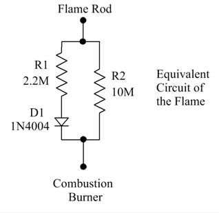
Flame Rod Wiring Diagram

Arduino Flame Sensor Interface

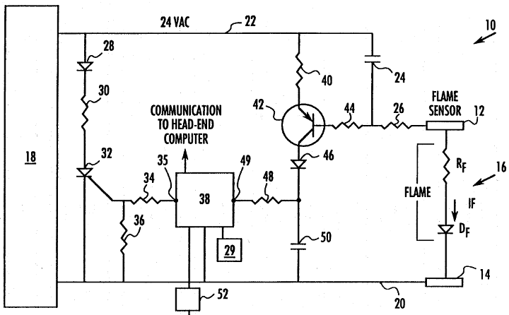
Flame Detector Circuit
Pilot Light Flame Sensor For Burning Man Art
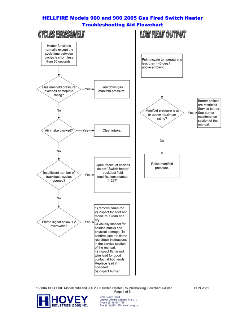
Each model features field select able trial for ignition tfi.
Flame rod wiring diagram. Step instruction 1 set switch of the meggar tester to the 500 setting and remove cable from the flame rod. Number of relay module to be used to 12. Use wflame rods or photocells. Disconnect power supply before beginning installation to prevent electrical shock and equipment damage.
12 pid and wiring diagram. Conversion wiring diagrams for rm7890 the diagrams and instructions contained in this booklet are for converting the following models of primaries and. Conversion wiring diagrams for rm7895. Table of contents operation parts drawing parts list wiring diagram front glass removal upper light replacement lower light replacement main onoffflame control replacement flame rod and motor replacement circuit board replacement audio board replacement page 2 page 3 page 4 page 5 page 6 page 7.
Table 2 meggar test instructions. Flame rod manual 372001 20 rev a 6. A 65vac signal is ap plied to the flame rod. But i found at the ultra manual they reference checking the flame signal using a voltage check to ground and it should be at least 4 volts dc from the electrode connection to ground 4 to 9 according to the wiring diagram manual.
Wiring diagram page 6 light bulb replacement page 7 ledswitch harness replacement page 9 light dimmer switch replacement page 10 flame speed control replacement page 11 flame motorflame rod replacement page 12 heater onoff switch replacement page 14 heater assembly replacement page 15. There are three different models to the veri flame line. Additional pid and wiring diagrams are provided in a separate application note. If you wnat to check the info i found the flame signal instructions are at.
The no purge the purge and the modulation models. There may be more than one disconnect involved. 7800 series conversion wiring diagram from r4138a b c d device to be modernized m3307 rm7838a os. 2 clip the black lead clamp of the meggar tester to the end of the kanthal rod of the sparkflame rod assembly.
The eclipse combustion veri flame single burner monitoring system controls the start up sequence and monitors the flame of single gas oil or combination gasoil burners. Conversion wiring diagrams for rm7838a. Wflame rods or photocells. Found to comply with the limits for a class b computing.
Turn off gas supply before starting installation. Dimplex 26 parts and service manual. 2 1 installation 13 pid and wiring diagram examples prv 103 ys 101. C7005ab gas pilot and flame rod assemblies 5 60 2033s4 wiring caution 1.
Use wflame rods photocells or c7012ac.

Flame Failure Monitor

Flame Gas And Smoke Detector Circuit Scheme

Flame Detector Circuit
Burner Ignition And Flame Monitoring System Patent 0071174

Flame Detector Circuit

Measuring Flame Signal And Cleaning Flame Sensors

Ruud Propane Furnace
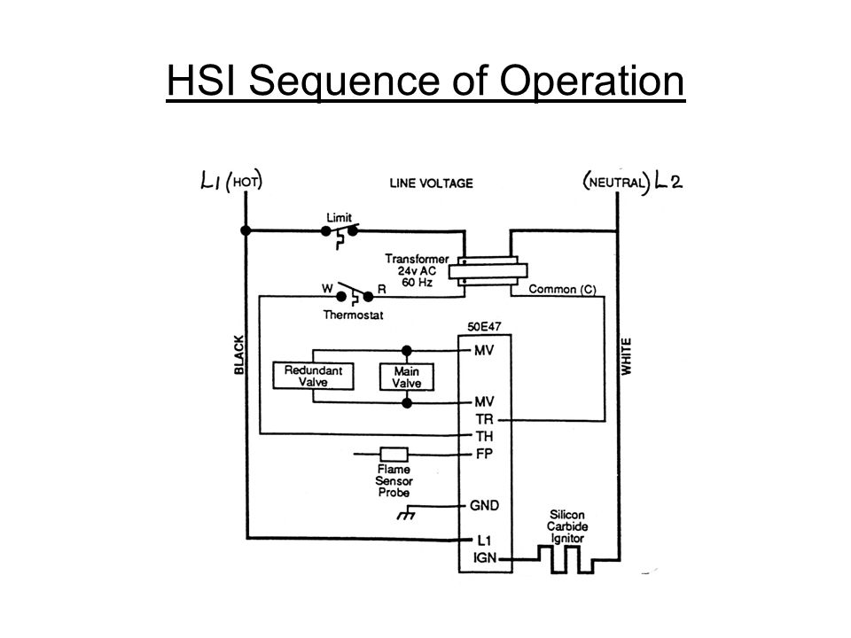
Gas Furnace Controls Part Ppt Video Online Download

Ra890 Relays Industrial Controls
Ruud Propane Furnace
Sp2017 006 0 Burner Troubleshooting

Ruud Propane Furnace
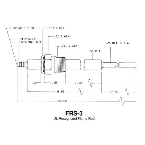
Flame Rods Results Page 1 Stromquist Company

Flame Detector Circuit
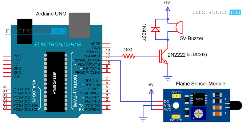
Arduino Flame Sensor Interface Working Circuit Diagram Code
Flame Rod Wiring Diagram Schematics Online
Ruud Propane Furnace

Flame Rectification Circuit Flame Proving Signal Measurement
