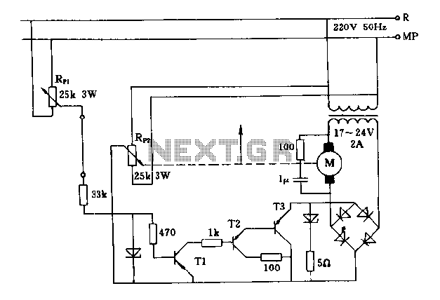
Servo Controller Wiring Diagram

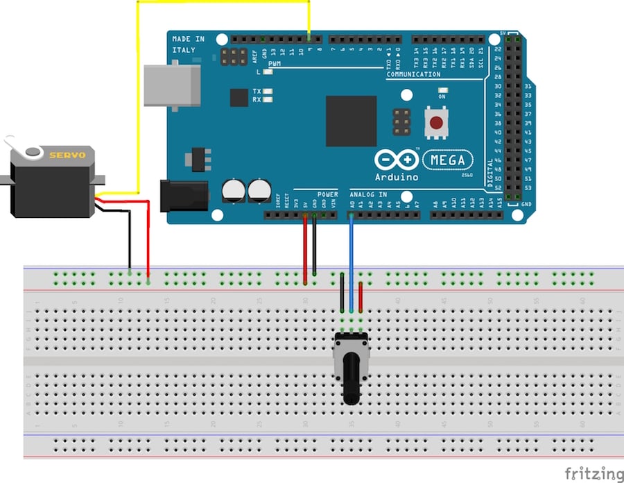
Servo motor control with an arduino june 03 2015 by tim youngblood.
Servo controller wiring diagram. There is an industry standard for resolver wire colors that most manufacturers choose to use. Attaching servos and peripherals. Diagram for connecting. The servo controller regulates the shaft velocity of the brushless motor with encoder feedback which is decoded by an hctl2000 quadrature decoder.
If you ever plan to replace or test a resolver then you need to know the functions of each wire. Servo motor resolver wiring. This can be very difficult to determine with out a little knowledge and a voltmeter. The control voltage will control the position of the servo motor connected to the output.
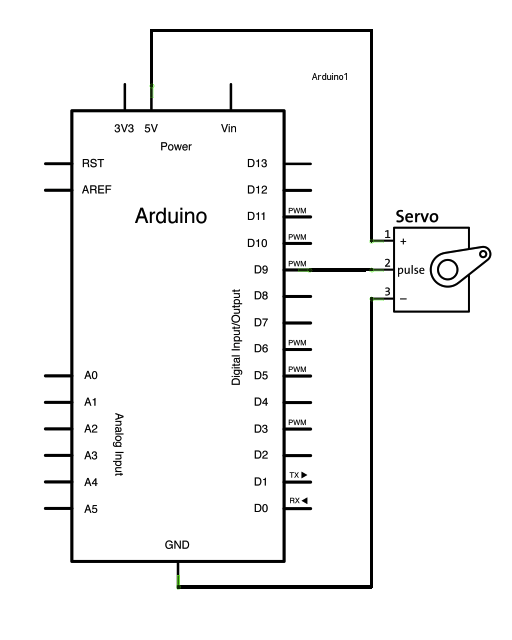
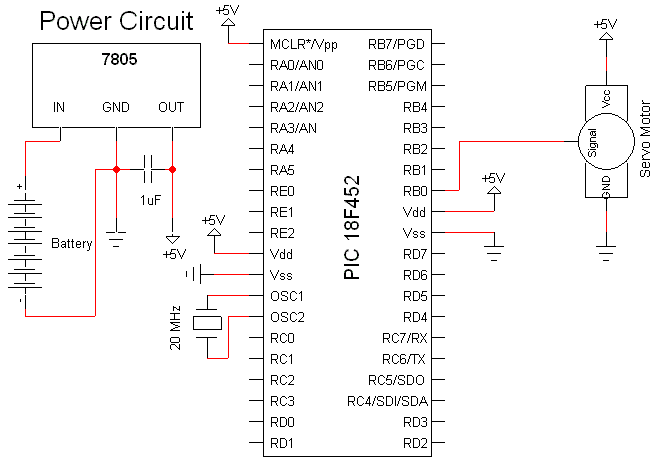
The best thing about a servo motor is that it can be connected directly to an arduino. An in circuit serial programming connector is provided on the pcb to allow for in board reprogramming of the pic micro controller. Choosing a backup generator plus 3 legal house connection options transfer switch and more duration. These colors are as.
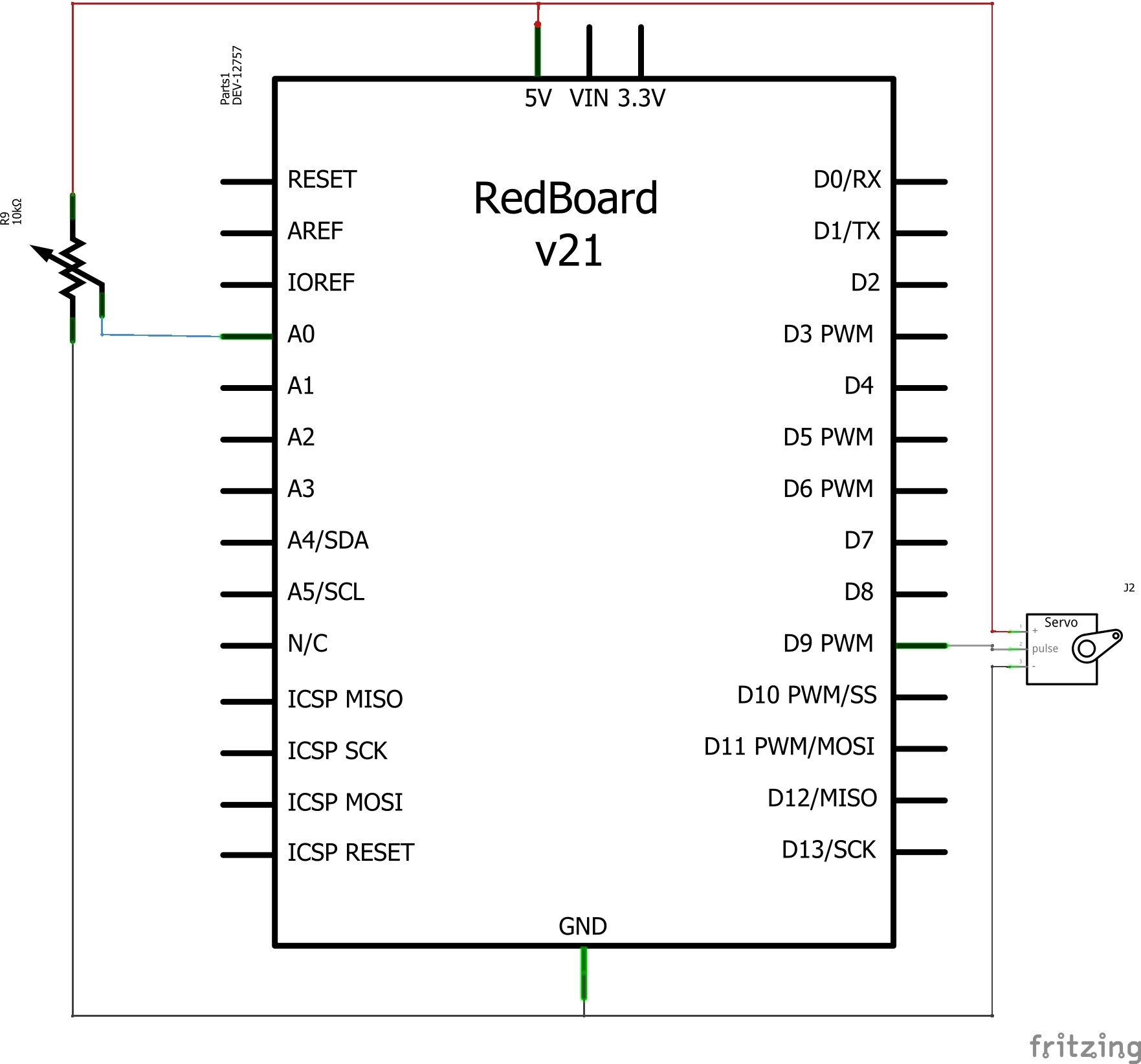
Wiring examples 7b. Servo red wire 5v pin arduino. 0 volt causes the servo to remain at one end and 10 volts to other end. A3936 three phase pwm motor driver.
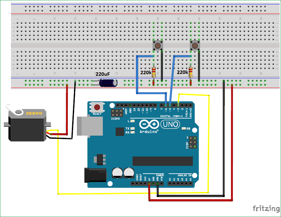
Connect to the motor to the arduino as shown in the table below. Servo controller ii com data alt dec 12 28v motor status motor status limit limit home p sync an in 5v gnd. Declination altitude is the same wiring. Servo ii wiring diagram 2012 11 24 5850 6250 pec.
Refer to the installation and wiring chapter of the user manual for more detailed wiring information. Support pololu maestro servo controller users guide 7. 0 volt causes the servo to remain at one end and 10 volts to other end. Bailey line road recommended for you.
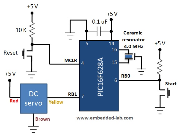
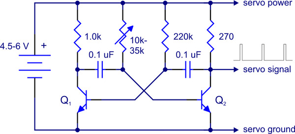
Servo motor driver may be used to control a single servo or even a group of servo motorsin many projects where servo motor controlling is the mainstay of the task to be accomplished the controller must drive more than one servo. This wiring diagram shows basic wiring only and additional wiring configurations are possible for some io. Connecting to a microcontroller. When the control voltage changes the servo will move to the new position corresponding to the new control voltage value.
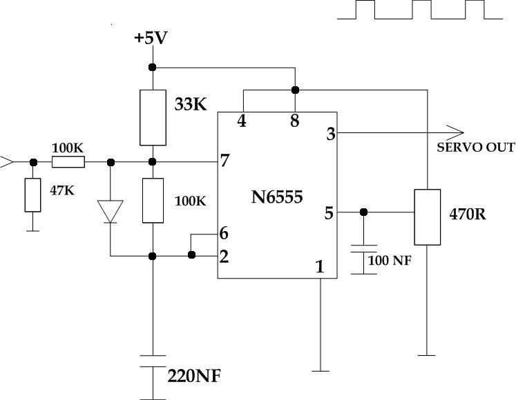
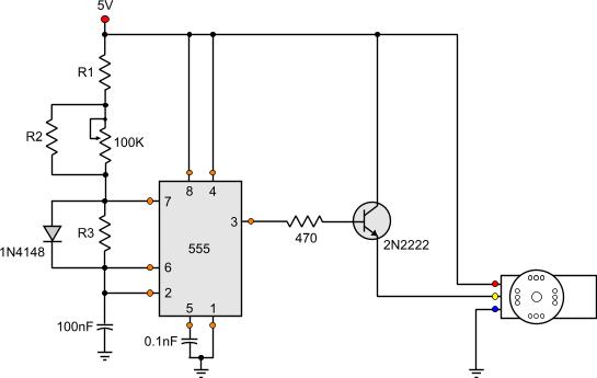
The control voltage will control the position of the servo motor connected to the output.


